The specification for the electrical system demanded the following requirements:
The system needs to function through an EMP blast.
No digital components, integrated circuits, green boards, etc.
Redundant and road side repairable
Function under water
A simple security system
Controls for the extra engine systems
Controls for a trailer and extra lighting.
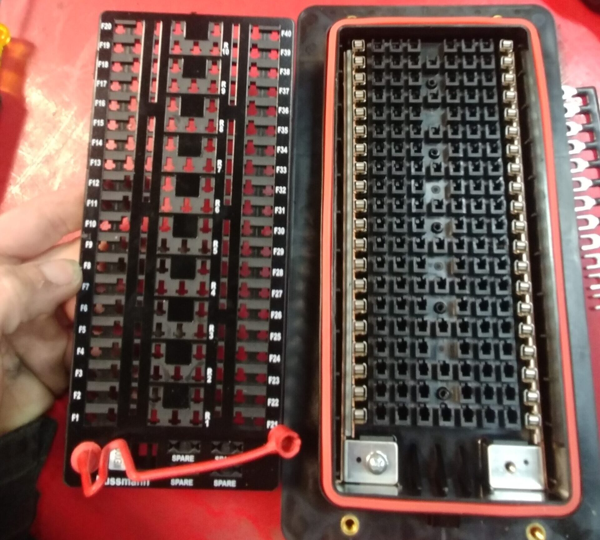
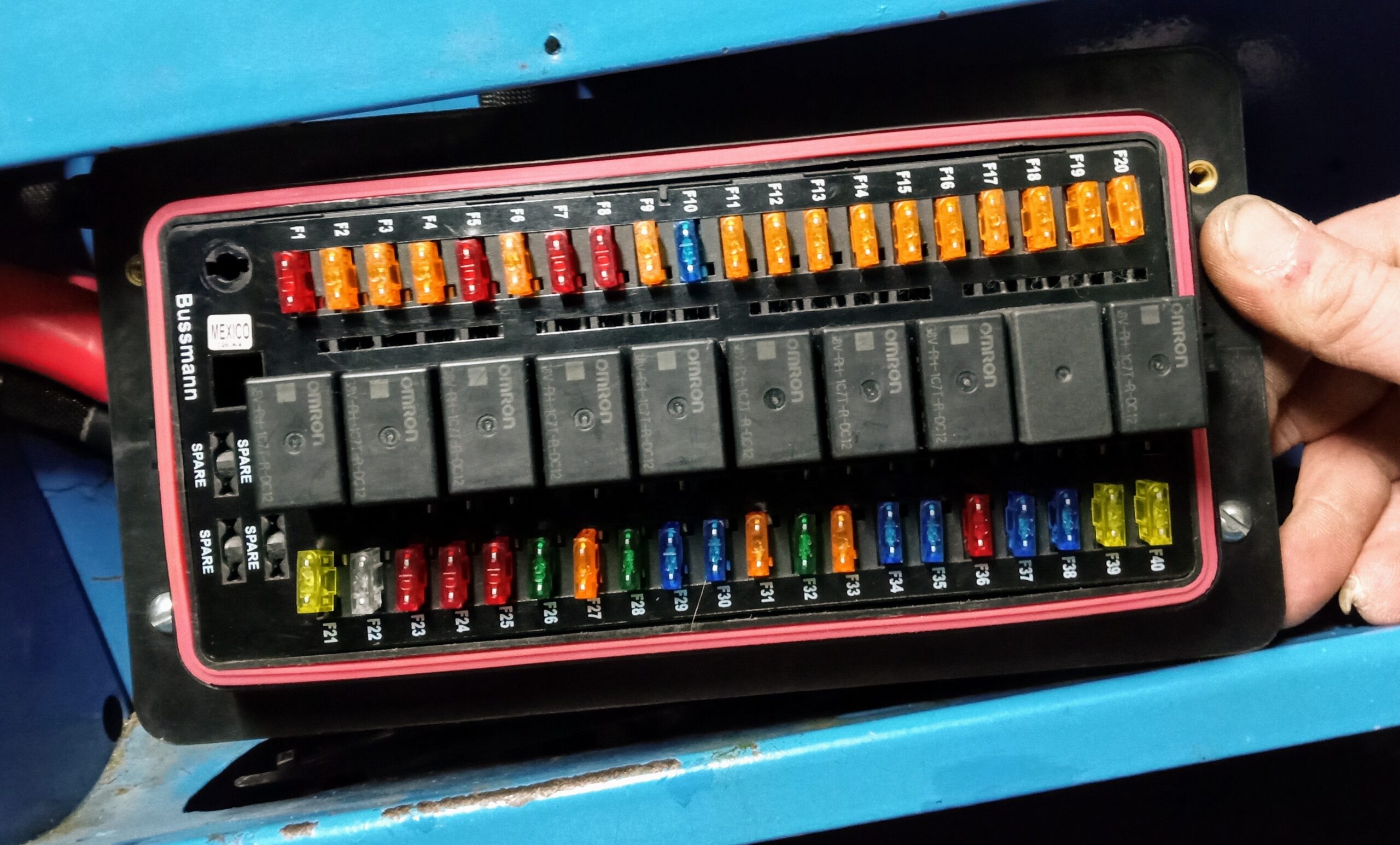
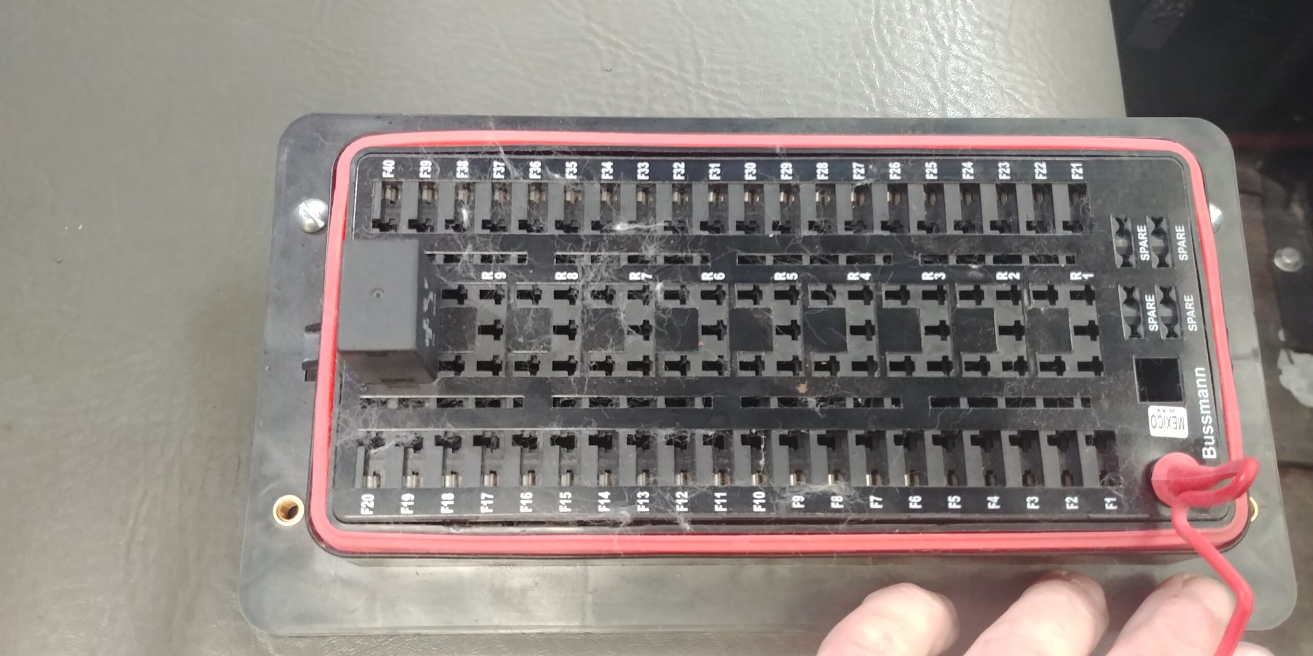
Improved fusing and electrical protection
Convert to Negative ground
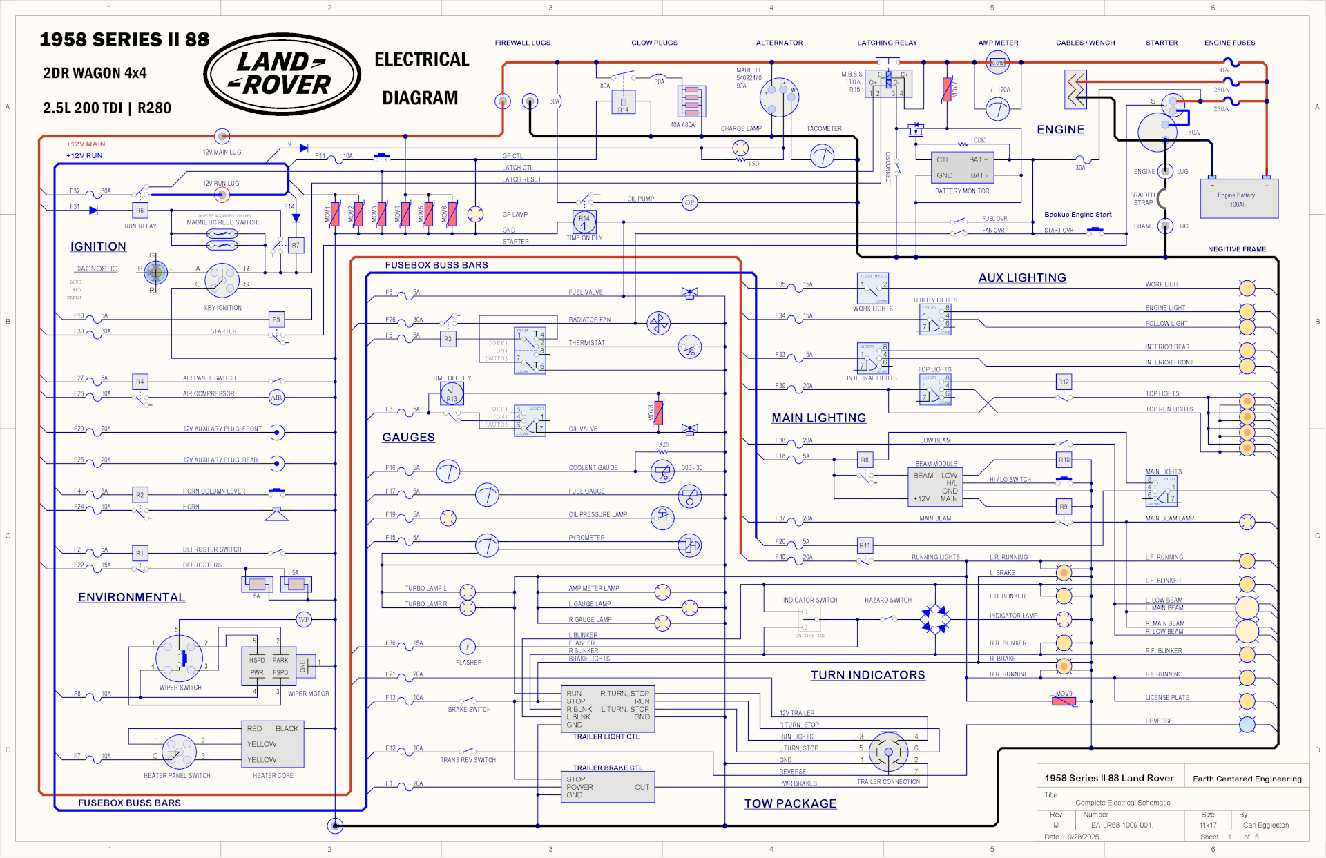
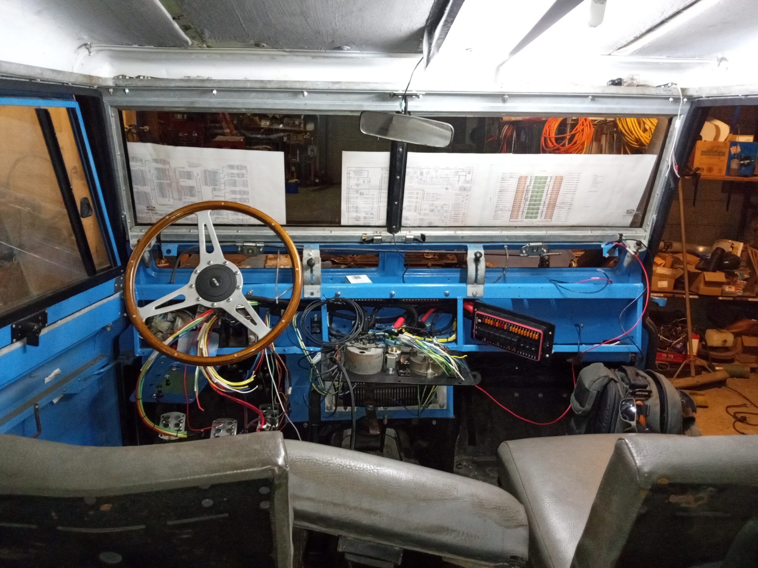
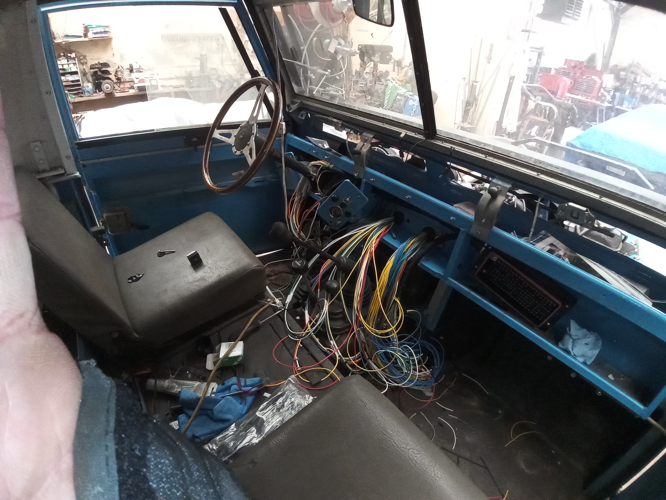
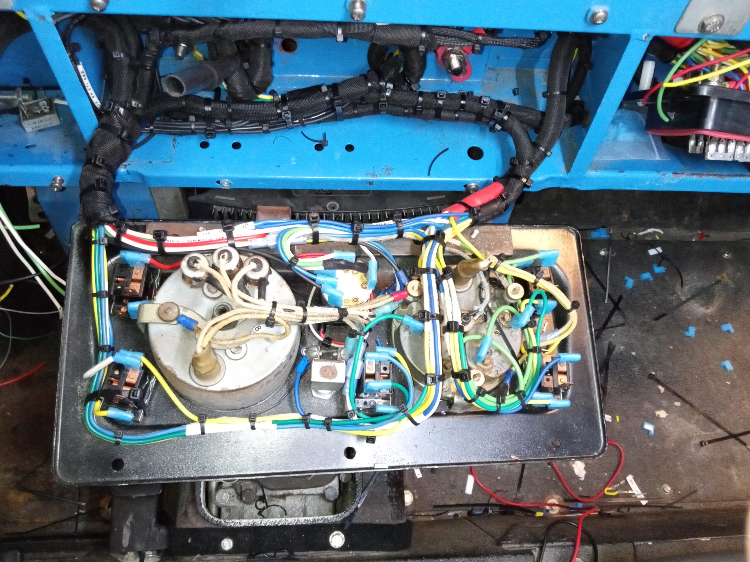
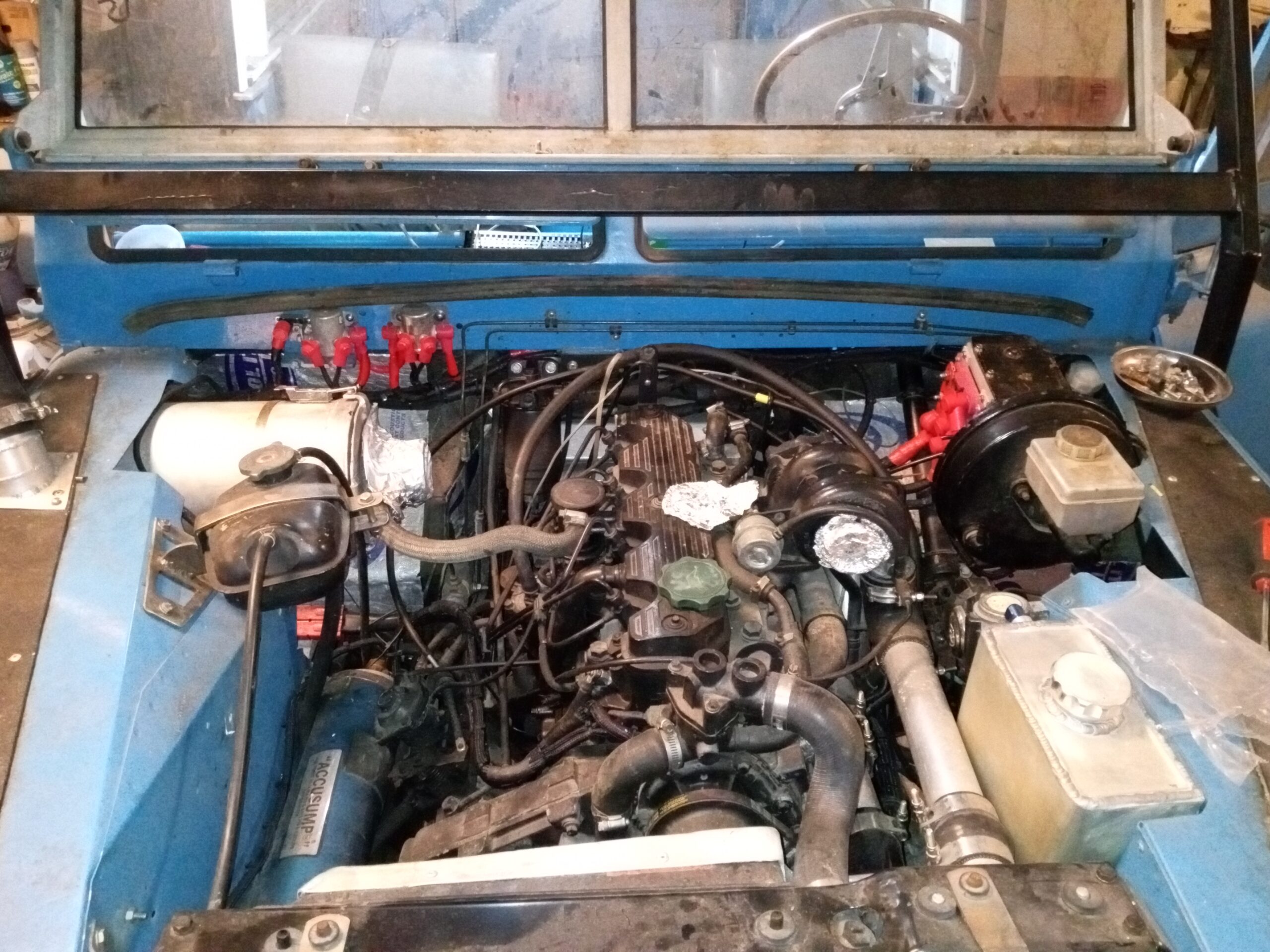
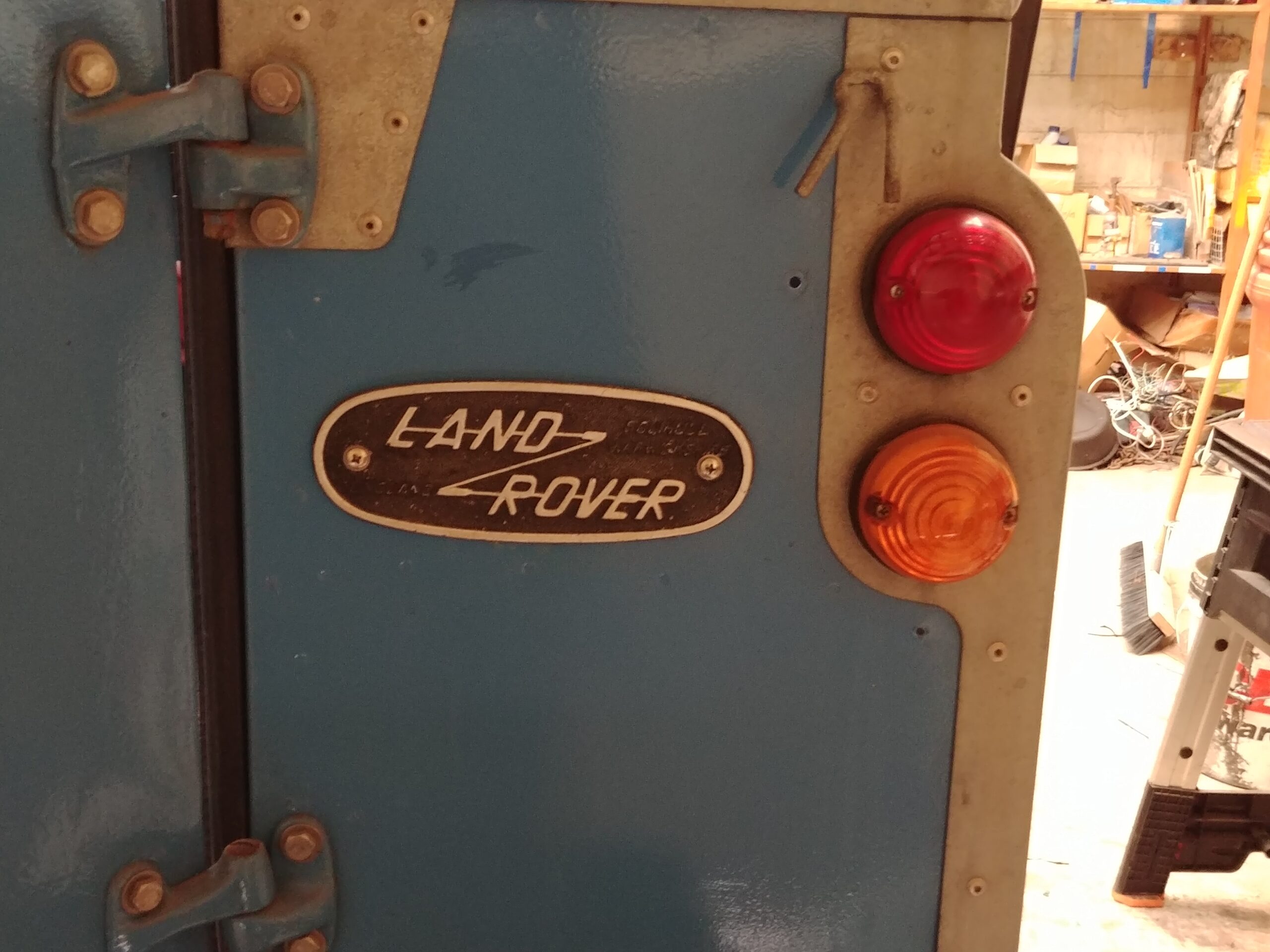
It was determined that to meet the specification we need to start from scratch. Remove all of the old wring and start with a fresh design. Top right is the electrical schematic and the machanical electrical drawings. all the mechanical drawing for the Rover Electrical system. Pictures below.
The electrical technology used on this build existed in the late 1950.
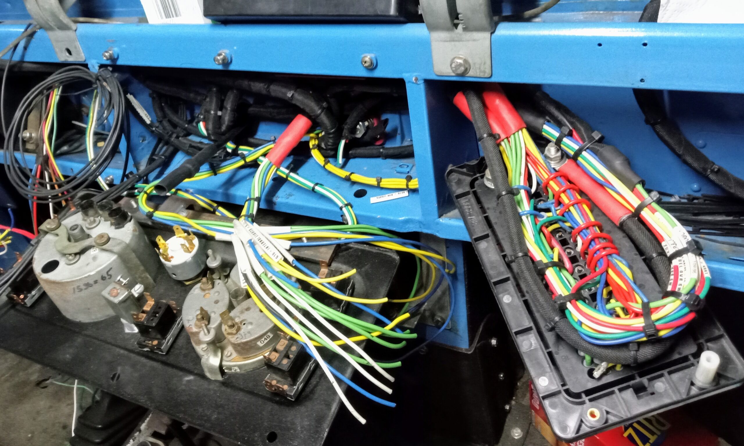
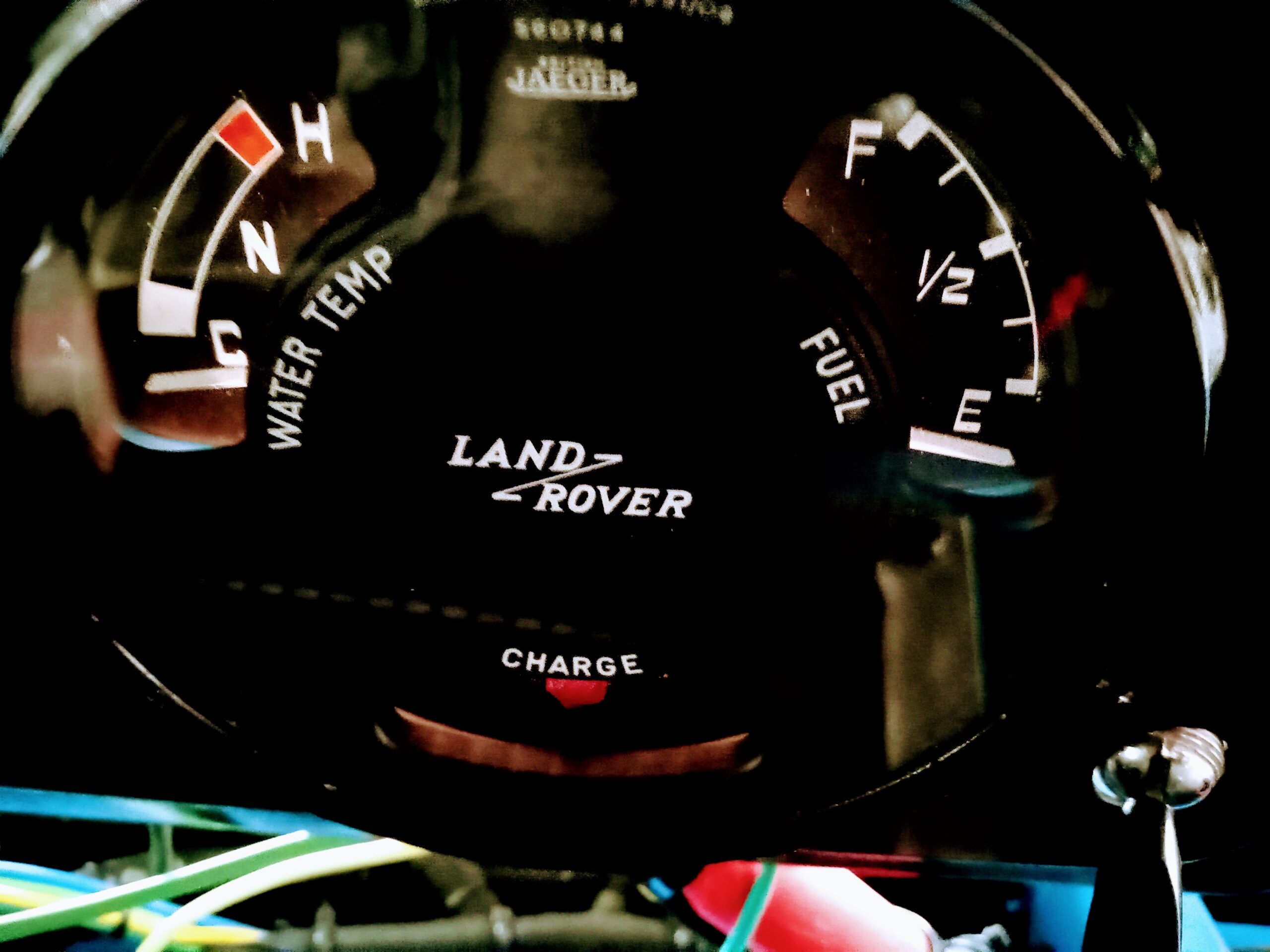
All switches and gauges are original Lucas 1950’s hardware.
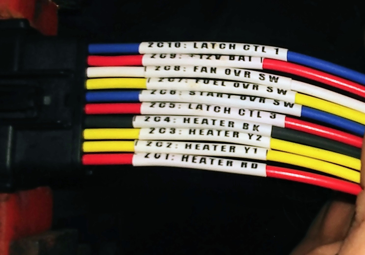
Every circuit is individually fused on both the control and load branches.
Each circuit follows current general automotive electrical practices.
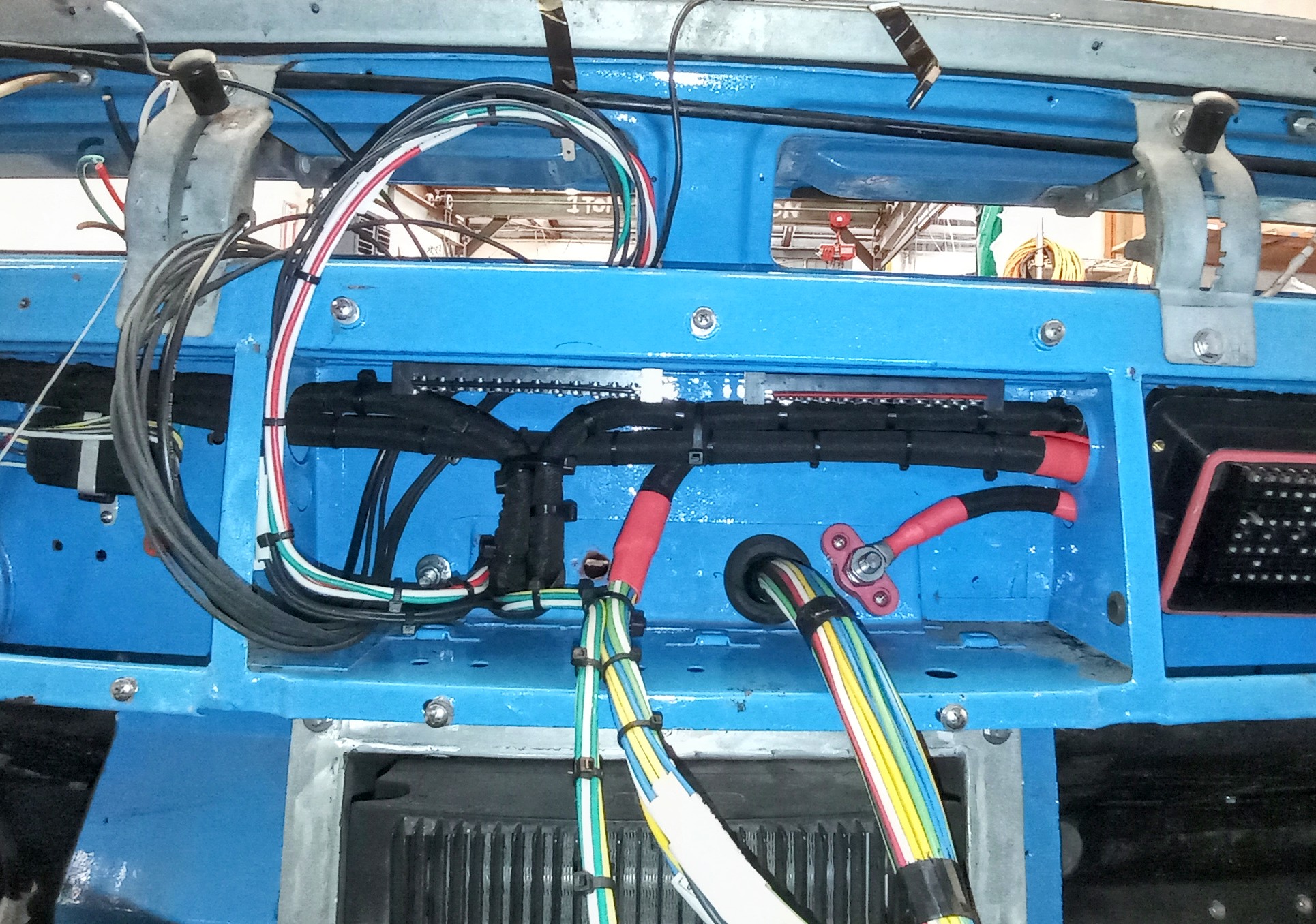
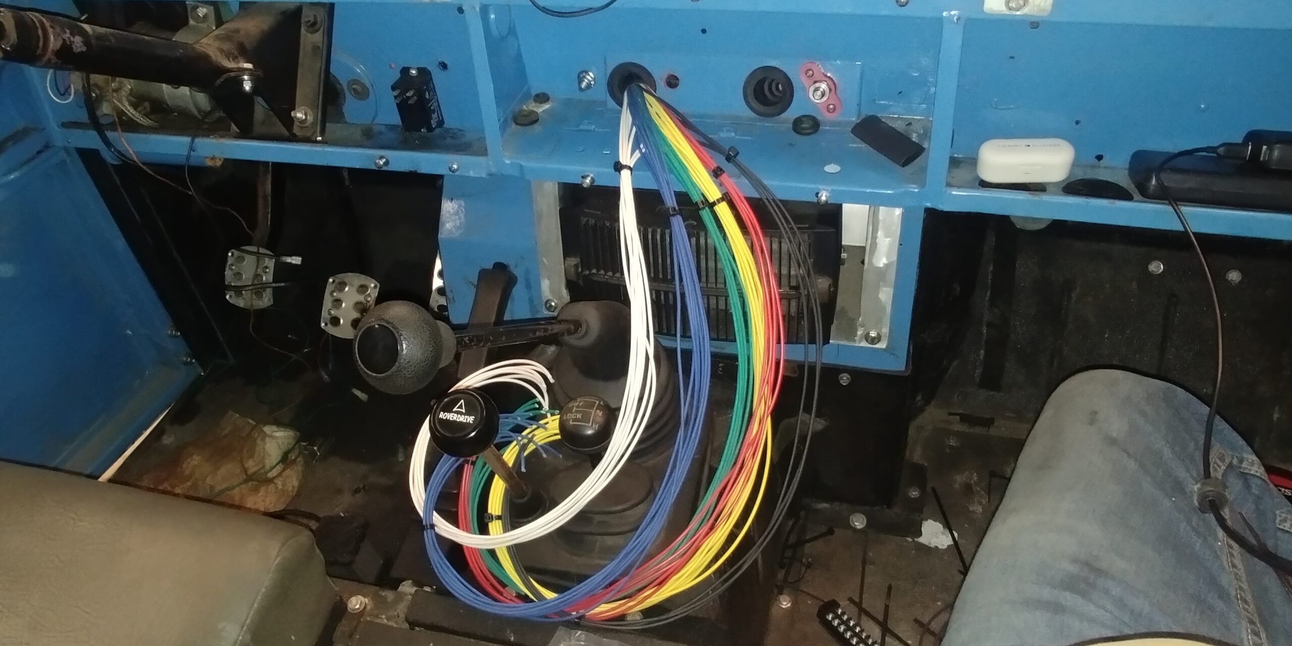
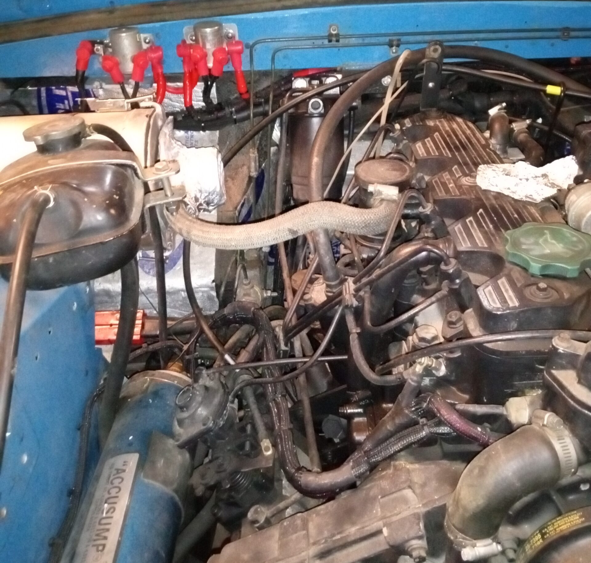
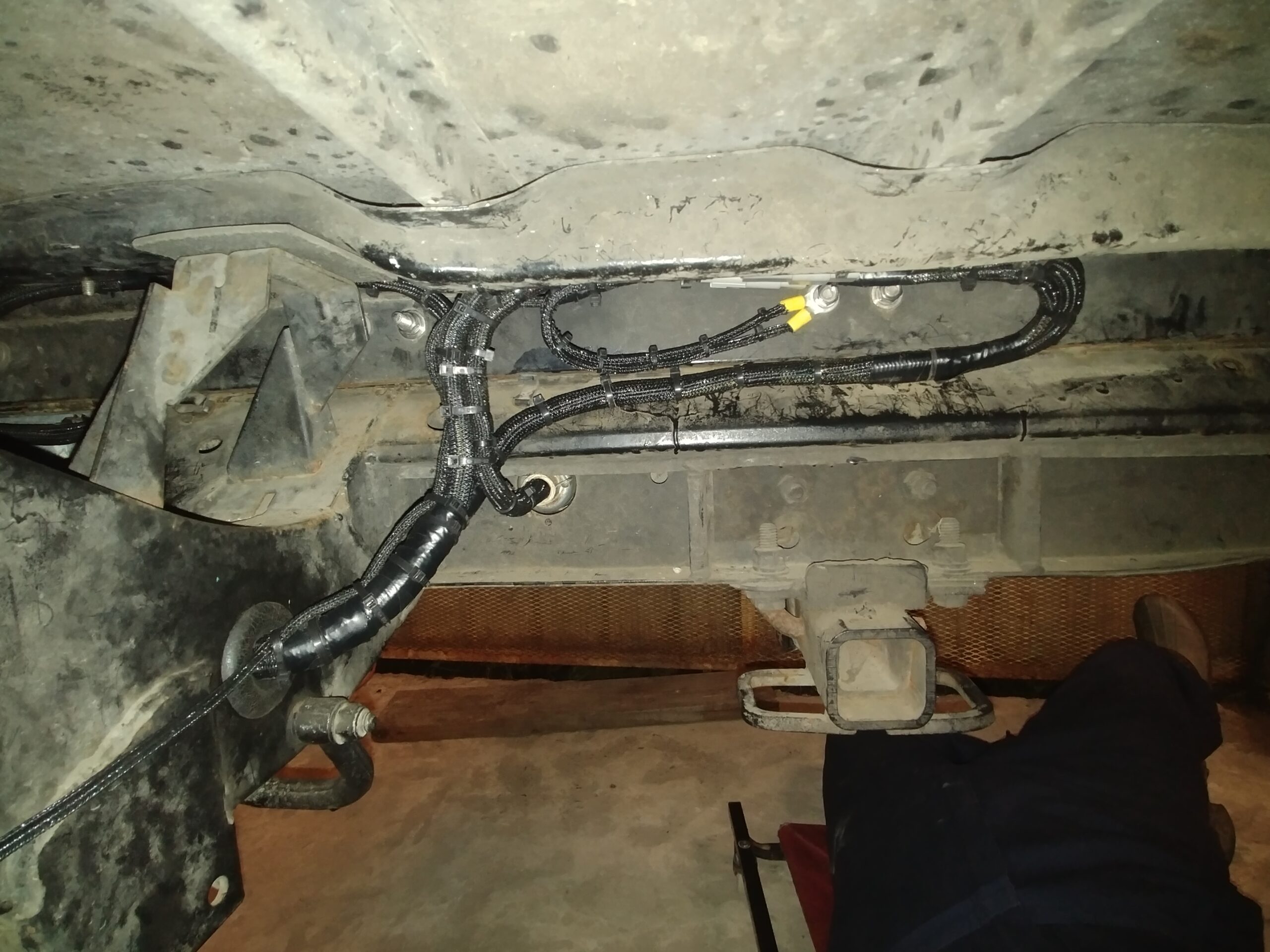
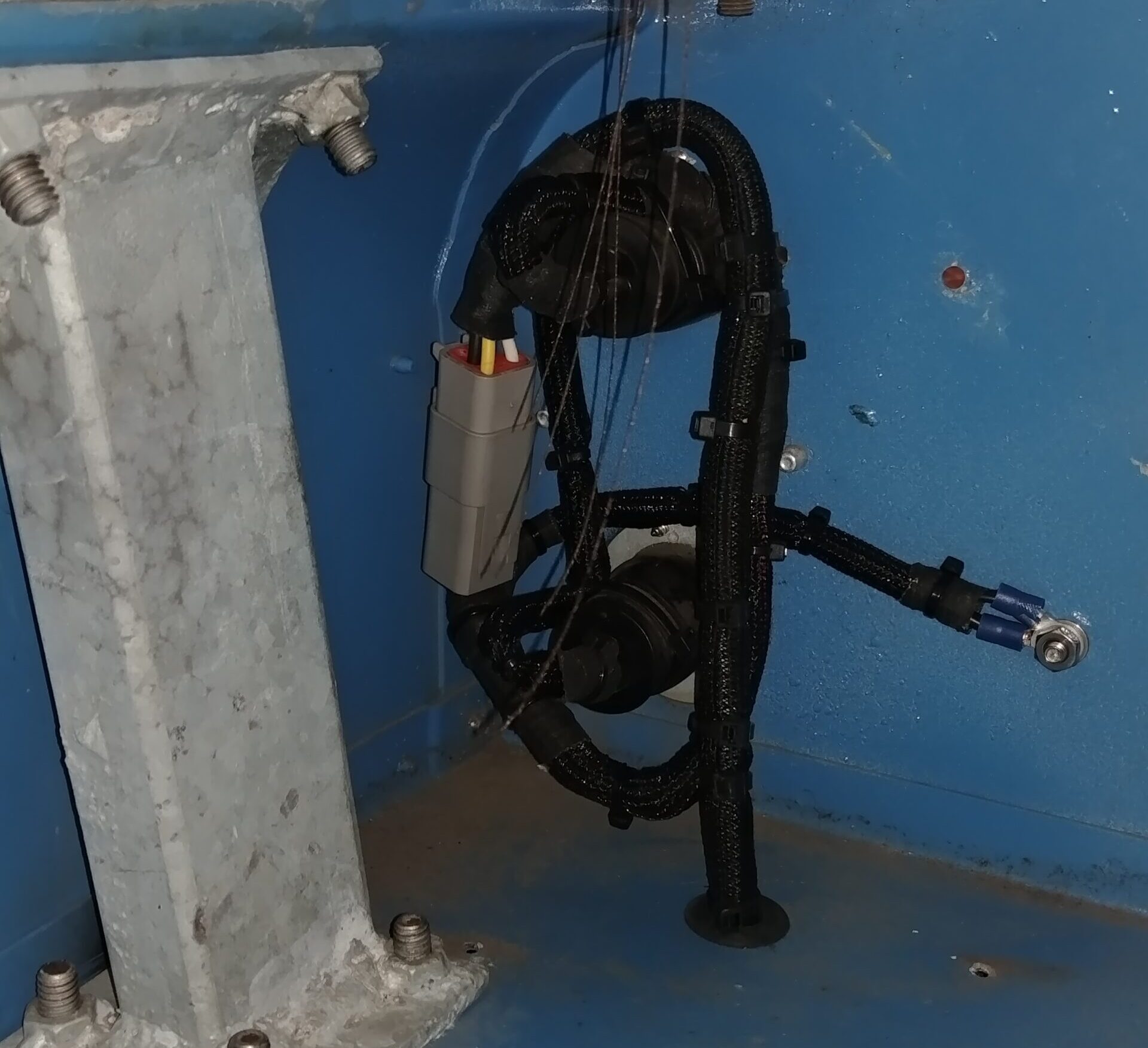
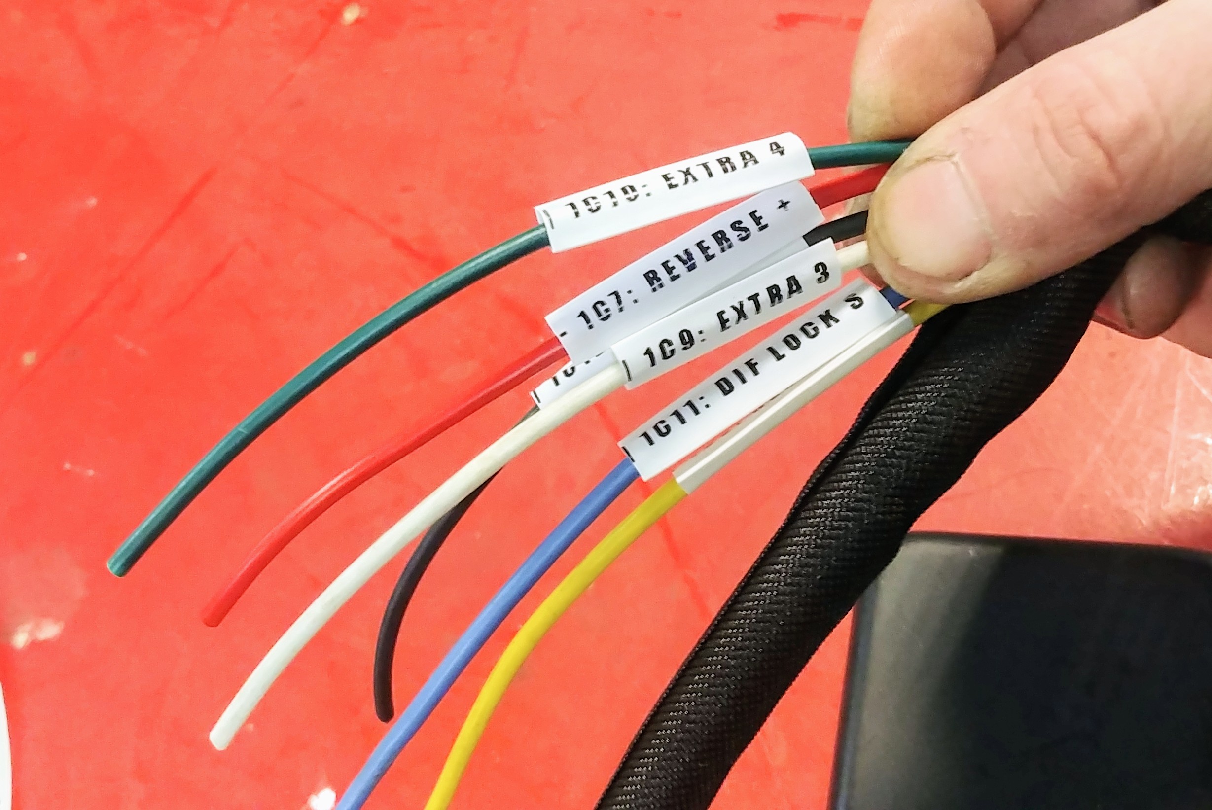
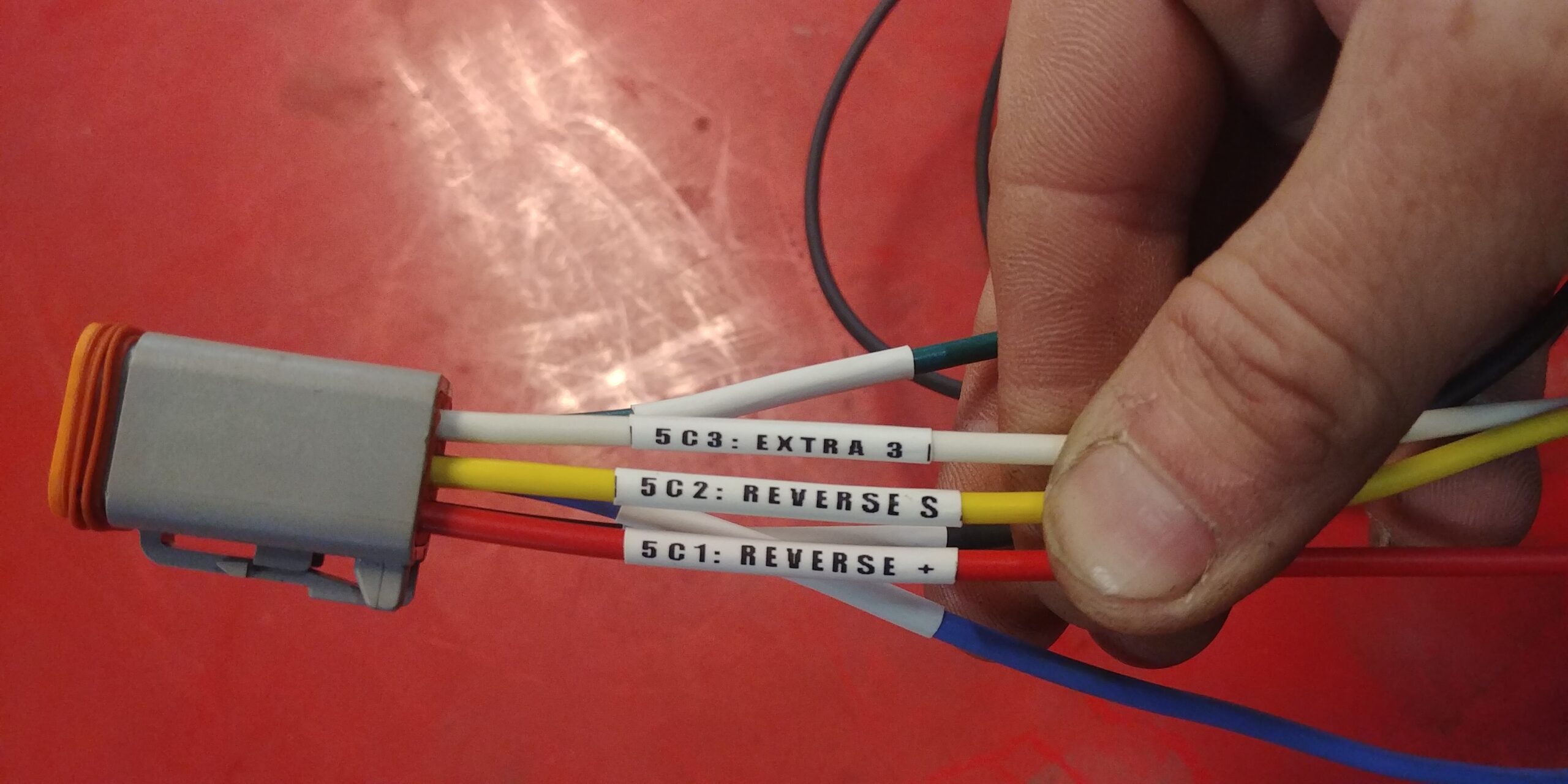
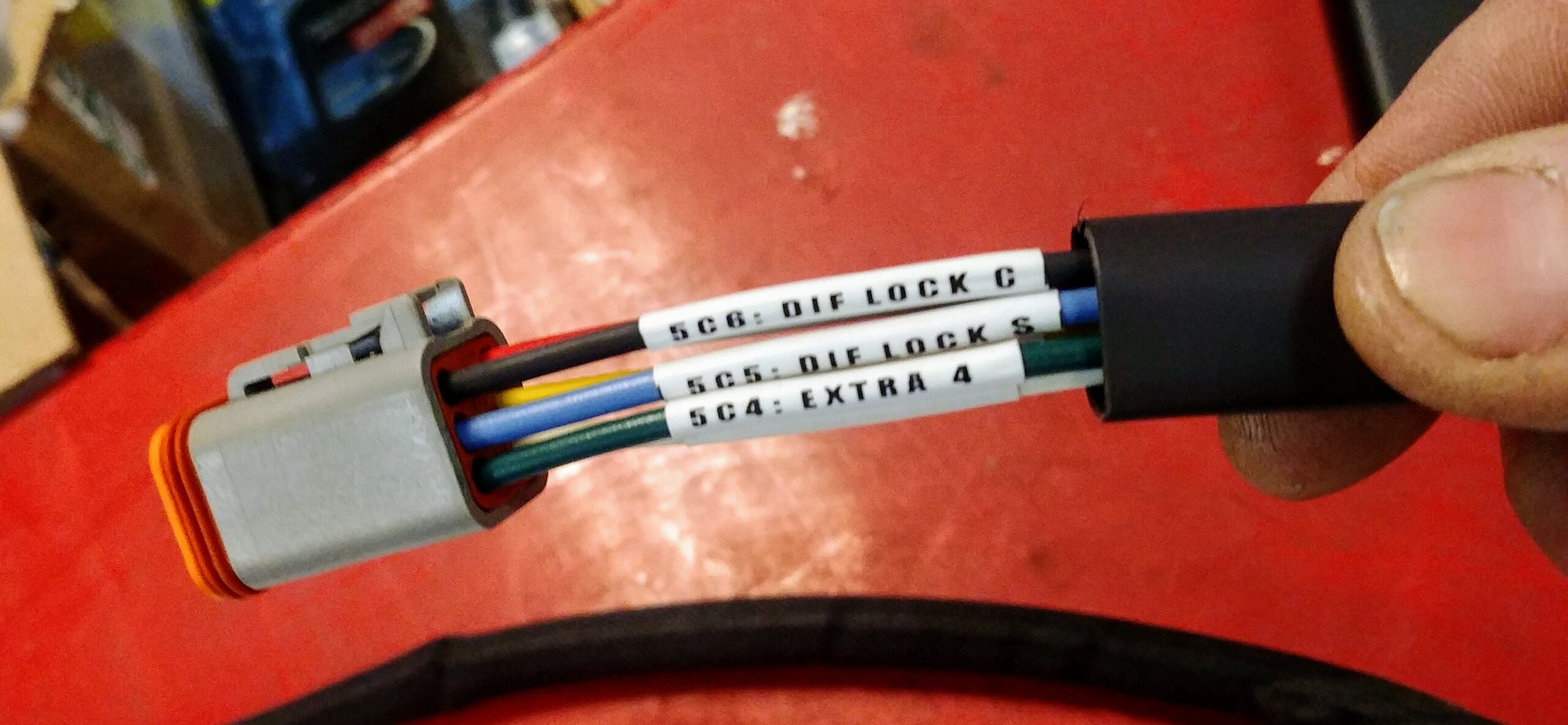
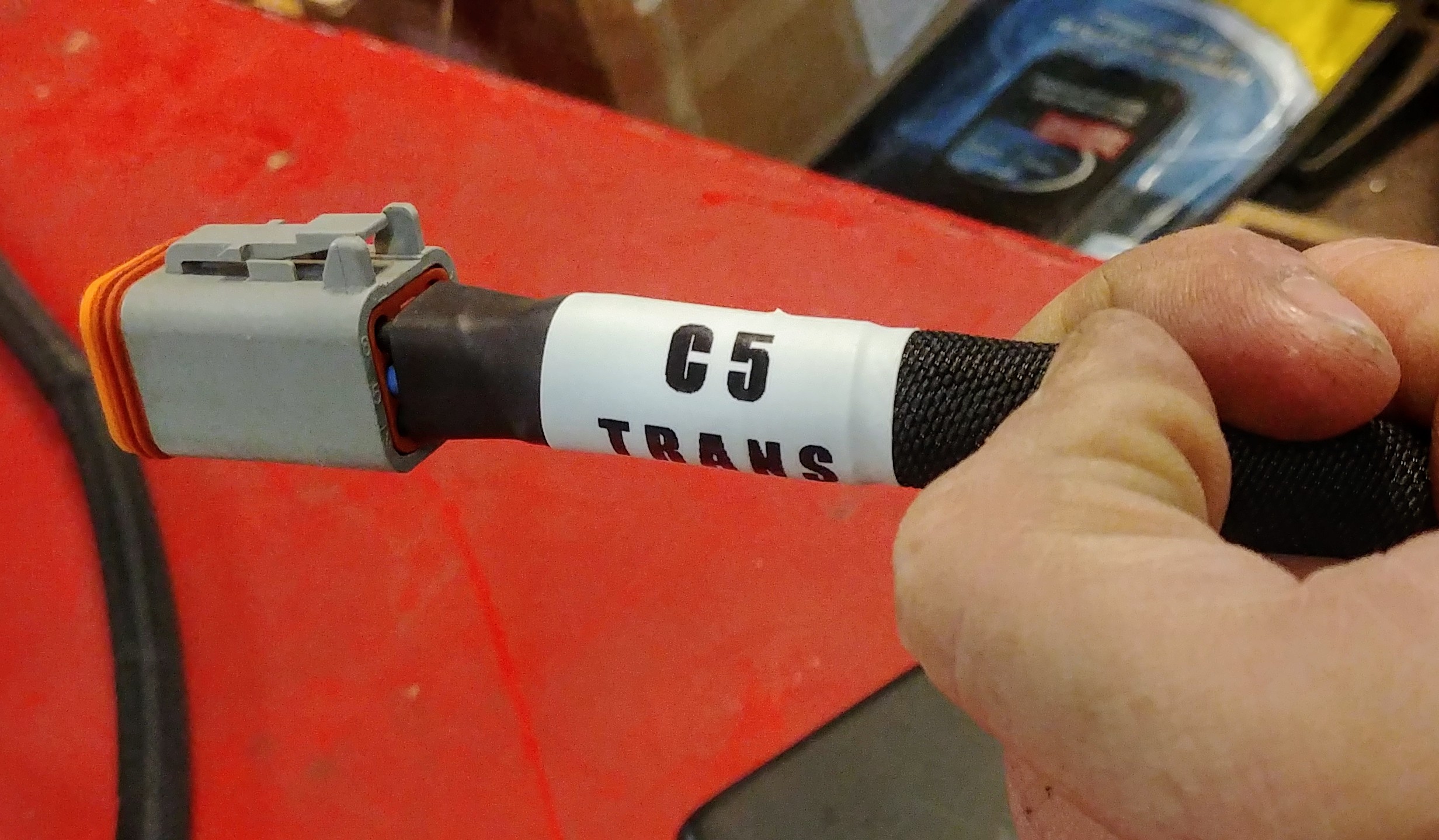
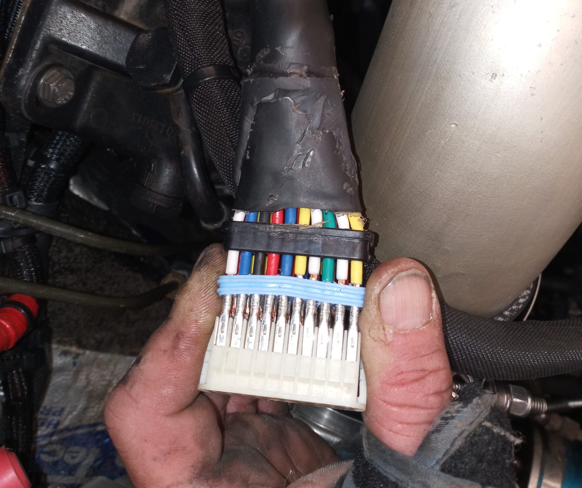
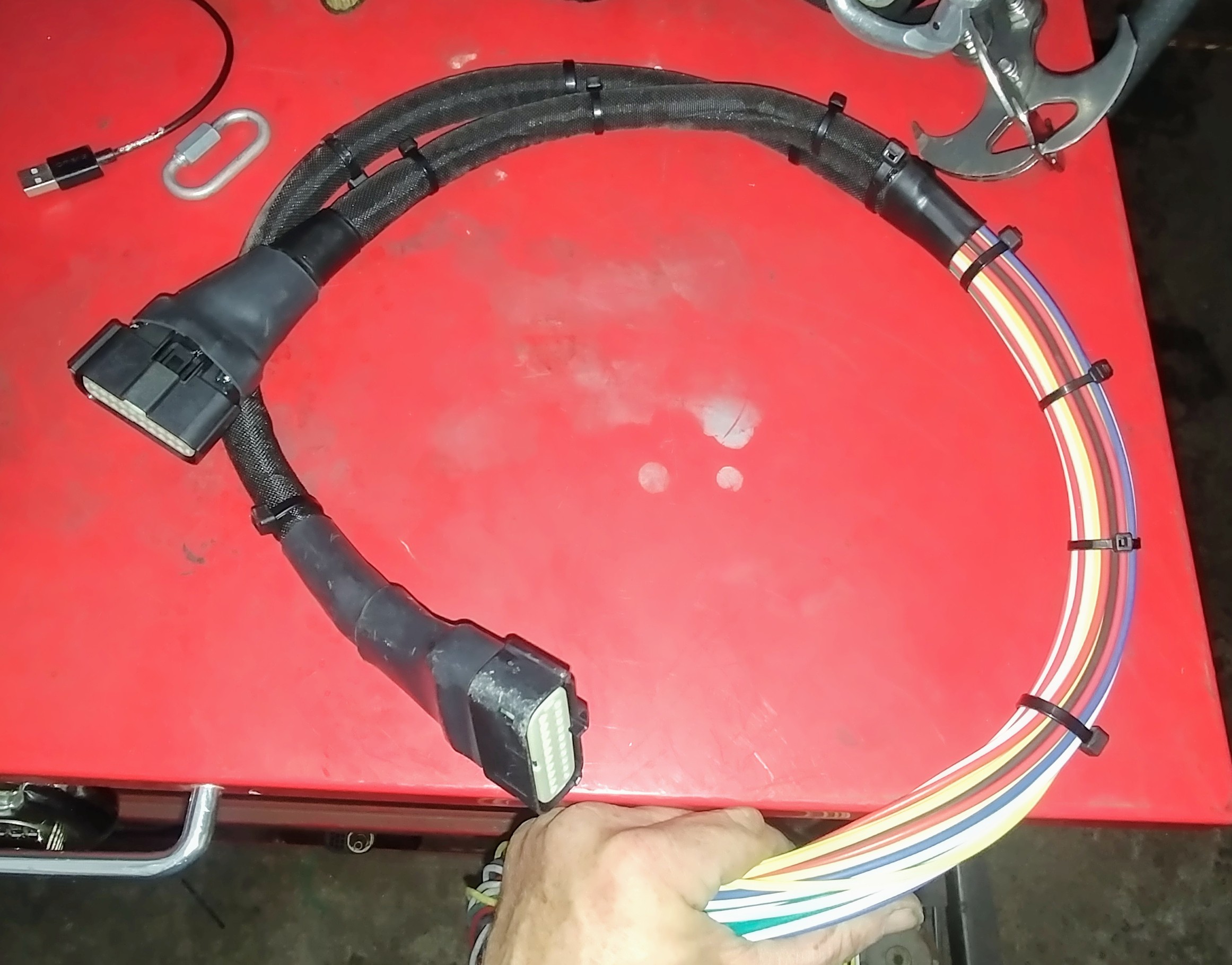
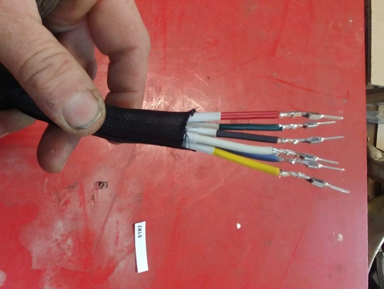
All harnesses are wrapped in a protective braided loom.
The system uses Molex and Amp water proof connectors.
The original Rover toggle switches are capable of controlling two lights.
The Rover toggle switches also allow for (Auto – On – Off)
control of the engine fan and oil filtration system.
All control logic is done with relays and few diodes.
When parks a voltage monitor disconnects the battery if voltage drops below 11 VDC. The battery is automatically reconnected when the key is turned and the remaining voltage will start the engine.
There is a three color diagnostic light plus a low voltage, temperature, and oil pressure warning lights.
Every time the vehicle is turned off a security feature locks out the ignition system and starter until deactivated with a wave of the hand.
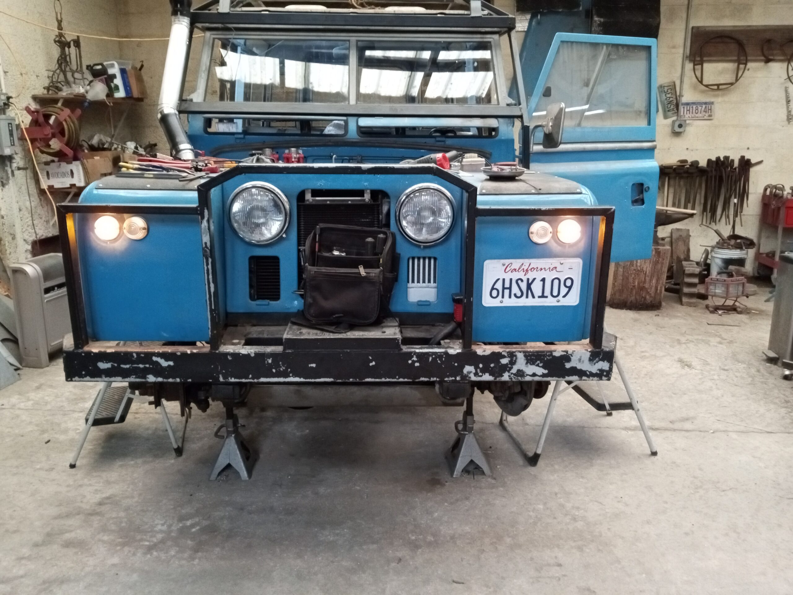
A 175A Anderson PowerPole connector mounted on the front bumper powers either a front wrench or jumper cables
In case of complete failure and destruction of the vehicle electrical system; A locked switch box can be connected to a complete backup system that will open the fuel valve, turn on the fan, and start the engine.